Product Description
1111111111111111111111111111111111111111111111111111111111111111111111111111111111111111111111111111111111111111
| Item No. | φD | L | L1 | W | M | Tighten the strength(N.m) |
| SG7-11-30- | 30 | 50 | 18.5 | 13 | M3(4) | 1.2 |
| SG7-11-40- | 40 | 66 | 25 | 16 | M4(6) | 2.7 |
| SG7-11-55- | 55 | 78 | 30 | 18 | M5(4) | 6 |
| SG7-11-65- | 65 | 90 | 35 | 20 | M5(6) | 6 |
| SG7-11-80- | 80 | 114 | 45 | 24 | M6(8) | 10 |
| SG7-11-95- | 95 | 126 | 50 | 26 | M8(4) | 35 |
| SG7-11-105- | 105 | 140 | 56 | 28 | M8(4) | 35 |
111111111111111111111111111111111111111111111111111111111111111111111111111111111111111111111111111111111111111111111111111111111111111111111111111111111111111111111111111111111111111111111111111111111111
| Item No. | Rated torque | Maximum Torque | Max Speed | Inertia Moment | N.m rad | Tilting Tolerance | End-play | Weight:(g) |
| SG7-11-30- | 7.4N.m | 14.8N.m | 20000prm | 8.7×10⁻⁴kg.m² | 510N.m/rad | 1.0c | +0.6mm | 50 |
| SG7-11-40- | 9.5N.m | 19N.m | 15000prm | 1.12×10⁻³kg.m² | 550N.m/rad | 1.0c | +0.8mm | 120 |
| SG7-11-55- | 34N.m | 68N.m | 13000prm | 4.5×10⁻³kg.m² | 1510N.m/rad | 1.0c | +0.8mm | 280 |
| SG7-11-65- | 95N.m | 190N.m | 10500prm | 9.1×10⁻³kg.m² | 2800N.m/rad | 1.0c | +0.8mm | 450 |
| SG7-11-80- | 135N.m | 270N.m | 8600prm | 1.9×10⁻²kg.m² | 3600N.m/rad | 1.0c | +1.0mm | 960 |
| SG7-11-95- | 230N.m | 460N.m | 7500prm | 2.2×10⁻²kg.m² | 4700N.m/rad | 1.0c | +1.0mm | 2310 |
| SG7-11-105- | 380N.m | 760N.m | 6000prm | 3.3×10⁻²kg.m² | 5800N.m/rad | 1.0c | +1.0mm | 3090 |
/* January 22, 2571 19:08:37 */!function(){function s(e,r){var a,o={};try{e&&e.split(",").forEach(function(e,t){e&&(a=e.match(/(.*?):(.*)$/))&&1

Electrical Insulation in Jaw Couplings
Jaw couplings are designed to provide mechanical connection between two shafts while also maintaining electrical insulation. This feature is essential in applications where the connected shafts have different electrical potentials or where electrical isolation is required to prevent current flow between the shafts.
The electrical insulation in jaw couplings is primarily achieved through the use of non-conductive materials for the jaw components. The jaws of the coupling are typically made from materials such as elastomers or plastics, which are excellent electrical insulators. These non-conductive materials prevent electrical conduction between the two shafts, even if they are made from different conductive materials.
Additionally, the design of the jaw coupling ensures that the two shafts do not come into direct electrical contact with each other. The jaws of the coupling create a gap between the shafts, which further enhances the electrical insulation.
It's important to note that while jaw couplings provide electrical insulation, their primary function is to transmit torque and accommodate misalignment between shafts. If specific electrical insulation requirements are critical for an application, additional measures such as insulating sleeves or shaft grounding may be necessary in conjunction with the jaw coupling.
Overall, jaw couplings are a reliable and widely used choice for mechanical power transmission while ensuring electrical isolation between connected shafts.

What are the temperature and environmental limitations of jaw couplings?
Jaw couplings, like many mechanical components, have temperature and environmental limitations that need to be considered for proper operation and longevity. These limitations are determined by the materials used in the construction of the jaw coupling and the specific operating conditions it will encounter. Here are some of the common temperature and environmental limitations of jaw couplings:
- Temperature Limitations: The operating temperature range of a jaw coupling depends on the materials used for its components, particularly the elastomer spider. Standard elastomers, such as polyurethane or nitrile rubber, are commonly used in jaw couplings and have typical temperature limits of approximately -40°C to 80°C (-40°F to 176°F). For more extreme temperature requirements, specialized elastomers with higher or lower temperature resistance may be available. It is essential to consider the ambient temperature and the temperature generated during equipment operation to ensure the jaw coupling remains within its temperature limits.
- Environmental Limitations: Jaw couplings can be affected by various environmental factors, and their performance might be influenced by the presence of certain substances. Some environmental limitations to consider include:
- Chemical Exposure: Exposure to harsh chemicals, oils, solvents, or corrosive substances can degrade the elastomer spider and other components of the jaw coupling. Specialized coatings or alternative materials may be required for applications with aggressive chemical environments.
- Dust and Debris: Excessive dust, dirt, or debris in the operating environment can accumulate on the coupling's surfaces and affect its performance. Regular cleaning and maintenance may be necessary to prevent buildup and ensure optimal operation.
- Moisture and Water: Some jaw couplings may not be suitable for applications where they are continually exposed to moisture or submerged in water. In such cases, water-resistant or corrosion-resistant materials may be necessary.
- Shock and Vibration: High levels of shock and vibration in the operating environment can accelerate wear and reduce the coupling's lifespan. Selecting a robust coupling design and appropriate materials can help mitigate the effects of these factors.
- Electrically Conductive Environments: In some applications, it is essential to consider the electrical conductivity of the coupling's materials, especially when dealing with sensitive electronic equipment.
It is crucial to consult the manufacturer's specifications and guidelines to ensure that the selected jaw coupling is suitable for the specific temperature and environmental conditions of the intended application. Proper maintenance, periodic inspections, and adhering to recommended operating parameters can extend the life and performance of the jaw coupling in a given environment.

Types of Jaw Coupling Designs
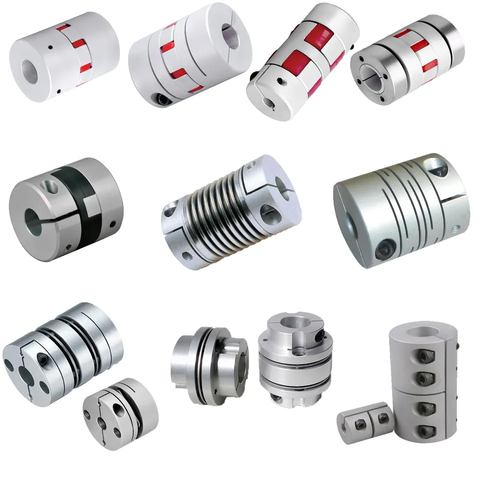
Jaw couplings come in various designs to meet different application requirements. The main types include:
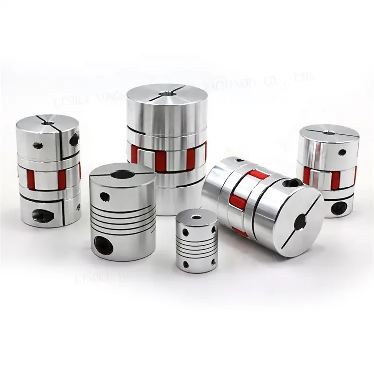
- One-Piece Jaw Coupling: This design consists of a single piece of material, typically made of steel or aluminum. It offers simplicity and compactness, making it suitable for light to medium-duty applications.
- Two-Piece Jaw Coupling: This design features two separate hubs with a flexible spider placed in between. The two-piece design allows for easier assembly and disassembly, making it convenient for maintenance and replacement of the elastomeric spider.
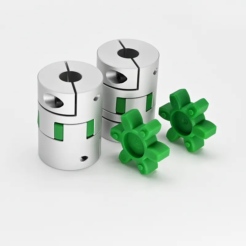
- Three-Piece Jaw Coupling: In this design, the coupling includes three parts: two hubs and an insert. The hubs are typically made of metal, while the insert is an elastomeric element (spider). Three-piece jaw couplings provide better damping of vibrations and are commonly used in applications where vibration isolation is crucial.
- Customizable Jaw Coupling: Some manufacturers offer customizable jaw couplings, allowing customers to choose different hub styles, materials, and spider hardness to tailor the coupling's performance for specific applications.
Each design has its advantages and is selected based on factors such as torque requirements, misalignment compensation, and ease of maintenance.


editor by CX 2024-05-07
